Wir verwenden Cookies, um Ihnen ein individuelles und reibungsloses Erlebnis zu bieten. Wenn Sie diese Website besuchen, stimmen Sie unserer Verwendung von Cookies zu. Wenn Sie es vorziehen, keine Cookies zu akzeptieren oder weitere Informationen benötigen, lesen Sie bitte unsere Datenschutzerklärung.
Notwendige Cookies Diese Cookies sind für die einwandfreie Funktion der Website unerlässlich und können nicht deaktiviert werden.
Analyse-Cookies Diese Cookies helfen uns zu verstehen, wie Besucher unsere Website nutzen.
Marketing-Cookies Diese Cookies werden verwendet, um Besucher zu verfolgen und relevante Werbung anzuzeigen.
Soziale Medien-Cookie Diese Cookies ermöglichen es Ihnen, Seiten und Inhalte in sozialen Medien zu teilen.
Fallls Sie wissen, in welche Kategorie Ihre Frage gehört, können Sie hier die Kategorie der häufig gestellten Fragen auswählen. Katalog:
Ergebnisse:
Q (Q&A-189|550):
The driver download page for my motherboard offers multiple drivers for Wi-Fi and Bluetooth. How can I determine which Wi Fi module is installed on my motherboard?(1/23/2026)
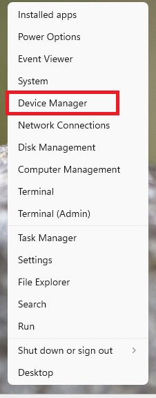
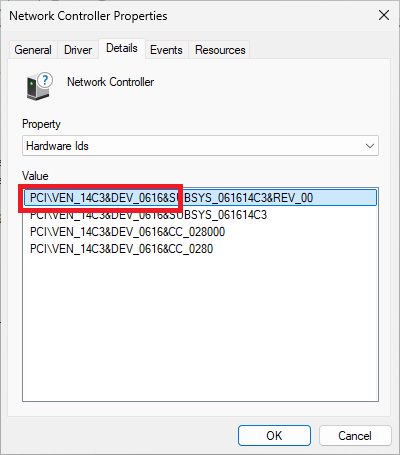
A:To check which Wi Fi module is used on the motherboard, you can have a look at the Hardware ID in Windows Device Manager. Please follow the steps below.
1. Right click the Windows Start button and select Device Manager.
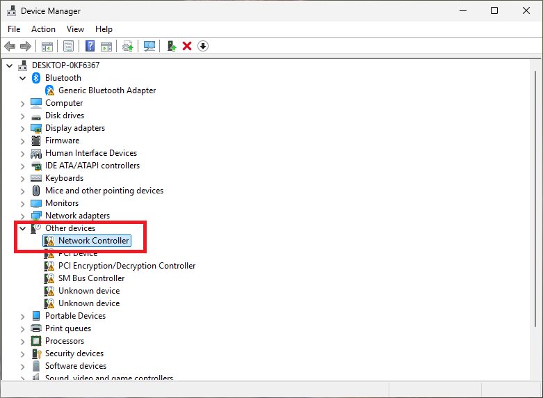
2. In Device Manager, check under Network adapters. If no Wi-Fi adapter is shown there, it can usually be found as a general network controller under Other devices.
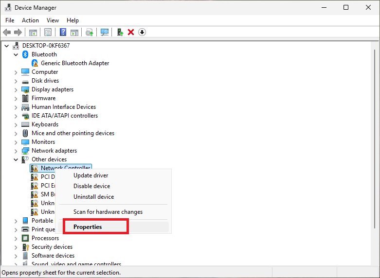
3. Right click the network controller and select Properties.
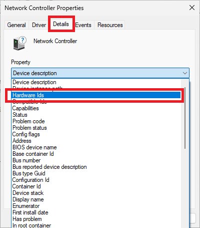
4. Go to the Details tab and choose Hardware IDs from the drop down menu.
5. Compare the displayed Hardware IDs with the corresponding reference information to identify the Wi Fi module model.
The example below uses AMD RZ616 for illustration.
Procedures
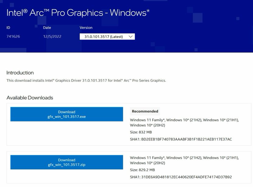
●Intel Graphics Card Driver
Go to Intel's official website to download and install the latest official graphics card driver.
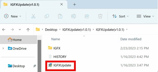
● Update the Graphics Card FW
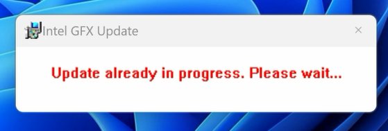
Step 1. Download and unzip IGFXUpdate(v1.01.1).
Step 2. Run "IGFXUpdate”
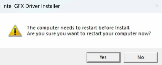
Step 3. Click Yes to restart the system.
Step 4. After the system has restarted, the FW update will begin.
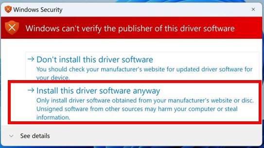
*If this message doesn't show up, please disable the "Secure Boot” in BIOS and try again.
Step 5. During the update, the following security message will pop up.
Step 6. Click on Install this driver software anyway.
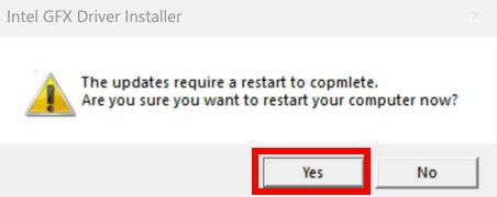
Step 7. The update process will proceed. The screen might blink during the update.
Step 8. Please restart your computer when the following prompt is shown.
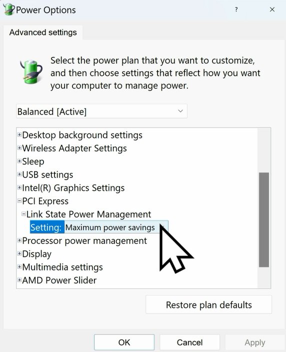
● Set PCIe Power to Maximum Power Savings
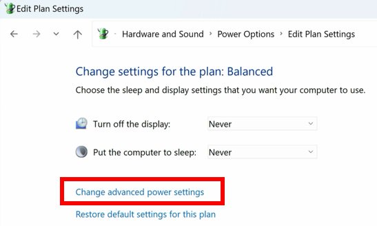
Step 1. Go to [Control Panel\Hardware and Sound\Power Options\Edit Plan Settings\Change] and click [Change advanced power settings].
Step 2. Scroll down to PCI Express\Link State Power Management and select Maximum power savings. Make sure to click apply to apply the changes.
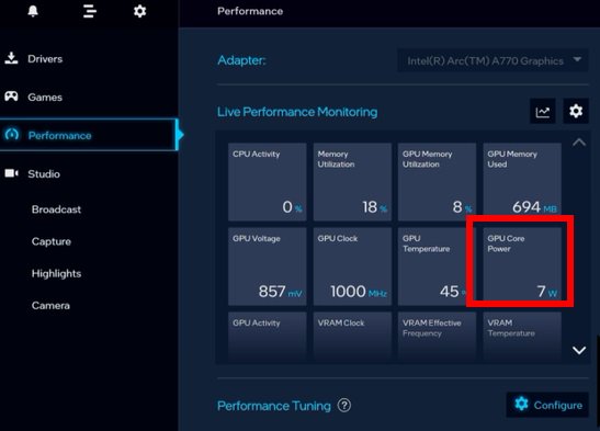
● Re-install the Graphics Card Driver and Check the GPU Power
Step 1. Reinstall the latest graphics card driver.
Step 2. To check the power consumption of the Intel ARC graphics card, please open Intel Arc Control and find the GPU Core Power.
BIOS Setting For ARC GPU Power Saving
● ASRock Intel Motherboard:
Required BIOS Version:
700-series motherboard: Please use the latest BIOS
600/500/400-series motherboard: Use the latest BIOS. It that does not work, please contact ASRock Technical Support. https://event.asrock.com/tsd.asp
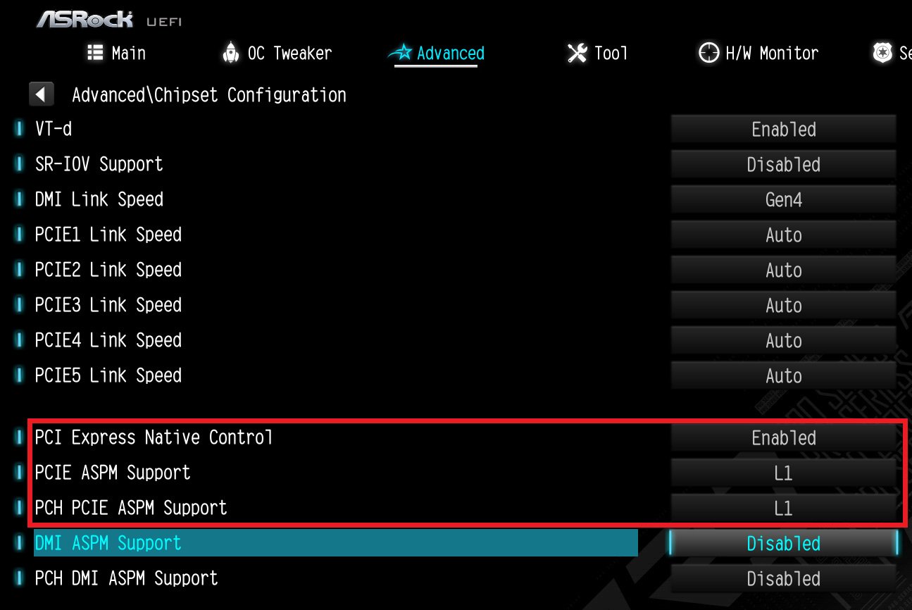
BIOS Settings for all ASRock Intel models:
In BIOS > Advanced > Chipset Configuration, apply the following settings.
PCI Express Native Control: Enabled
PCIE ASPM Support: L1
PCH PCIE ASPM Support: L1
● ASRock AMD Motherboard:
Required BIOS Version:
Platform
600 series
500 series
400 series
300 series
BIOS version
Any version
Not supported
BIOS Setting for all AMD models:
There is no need to change BIOS settings.
● Other brands motherboard:
Please contact your motherboard vendor for further assistance.
Power Consumption After Updating FW and Changing the BIOS Settings
Q (Q&A-170|517):
There is no display output after starting the system. What can I do?(8/9/2022)
A:Please try the followings:
1. First of all, check if the monitor cable (HDMI/DisplayPort) is connected properly to both the monitor and the motherboard or notebook.
2. Please try other monitor cables.
3. Monitor settings
-Press the icon above to select the specific monitor input that you are using, e.g. HDMI.
-Try another monitor input.
Other troubleshooting
-Test the monitor with another motherboard or notebook to check if the monitor is working.
- Please try the output of the other GPUs, as you might have multiple GPUs in your system. (One or more PCIe graphics cards and/or integrated graphics)
4. Check Power cord connection.
Q (Q&A-168|514):
Welches CNVi-WLAN-Modul ist mit meinem Motherboard kompatibel?(4/1/2022)
A:First please determine which type of WiFi/Bluetooth(BT) module you can use on your motherboard. Second, if you want to use CNVi, you will need to check which generation of CNVi your motherboard supports.
Which type of WiFi/BT module is supported on your motherboard?
In general, there are 2 types of WiFi/BT modules that can be used via a Key E M.2 socket.
One type uses a regular PCIe connection (for WiFi) and USB connection (for Bluetooth) via the M.2 socket.
The other type uses CNVi, which is available on specific Intel platforms only: https://www.intel.in/content/www/in/en/support/articles/000026155/wireless.html
On the Asrock website, please check the specifications of your motherboard to determine which type is supported on your motherboard. Here are some examples.
If you would like to use CNVi, please note that there are different generations of CNVi. The table below shows which chipset supports which CVNi generation.
Intel Chipset
Supported CNVi System Interface Type
Intel 300 series
M.2: CNVio
Intel 400 series
M.2: CNVio and CNVio2* *CNVio2 support only for Model Intel AX101, AX201, AX203.
Intel 500 series
Intel 600 series
M.2: CNVio and CNVio2
Checking the specifications of WiFi/BT modules
To check the "System Interface Type” of your WiFi module, please visit Intel® ARK for further information.
Step 2.
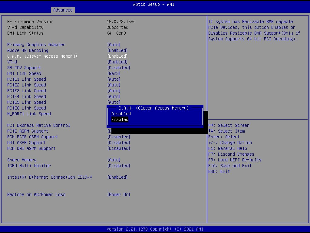
The C.A.M. (Clever Access Memory) option is supported when integrated graphics are disabled.
By default integrated graphics will be disabled when a PCIe graphics card is detected.
Please make sure the monitor is connected to the graphic card.
Step 3.
Please go to BIOS\Advanced\Chipset Configuration and enable "C.A.M. (Clever Access Memory)”.
Step 4.
Press F10 to save the setting and restart.
Q (Q&A-161|499):
Are there any limitations for M.2 sockets on Intel 500 series motherboards?(5/1/2021)
A:The availability of and speed supported by M.2 sockets on Intel 500 series motherboards may differ depending on which CPU is in use. (11th Generation or 10th Generation Intel Core processor)
For the specifications of each product, please refer to the tables below.
All of the M..2 sockets on the following models can be used in combination with 11th and 10th Generation CPUs.
Model
11th Generation
10th Generation
Z590 OC FormulaZ590 Taichi
M2_1: Gen4x4M2_2: Gen3x4+SATAM2_3: Gen3x4+SATA
M2_1: Gen3x4M2_2: Gen3x4+SATAM2_3: Gen3x4+SATA
Z590M Pro4
M2_1: Gen4x4+SATAM2_2: Gen3x4+SATA
M2_1: Gen3x4+SATAM2_2: Gen3x4+SATA
B560M Steel Legend
M2_1: Gen4x4M2_2: Gen3x4+SATA
M2_1: Gen3x4M2_2: Gen3x4+SATA
B560M-ITX/ac
M2_1: Gen4x4+SATA
M2_1: Gen3x4+SATA
H510M-HDV/M.2H510M/acH510M-ITX/ac
M2_1: Gen3x4+SATA
M2_1: Gen3x4+SATA
Some of the M.2 sockets on the following models can only be used in combination with an 11th Generation CPU.
※M.2 sockets may share lanes with PCIe slots or SATA ports. For detailed specifications, please refer to the product page.
Q (Q&A-153|489):
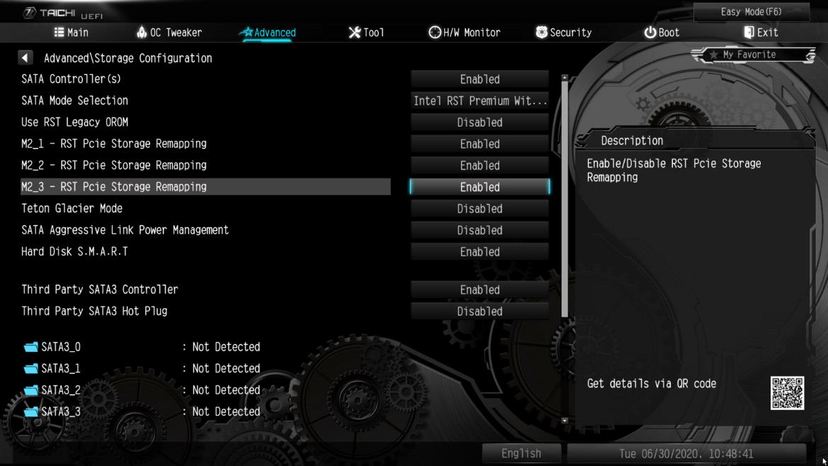
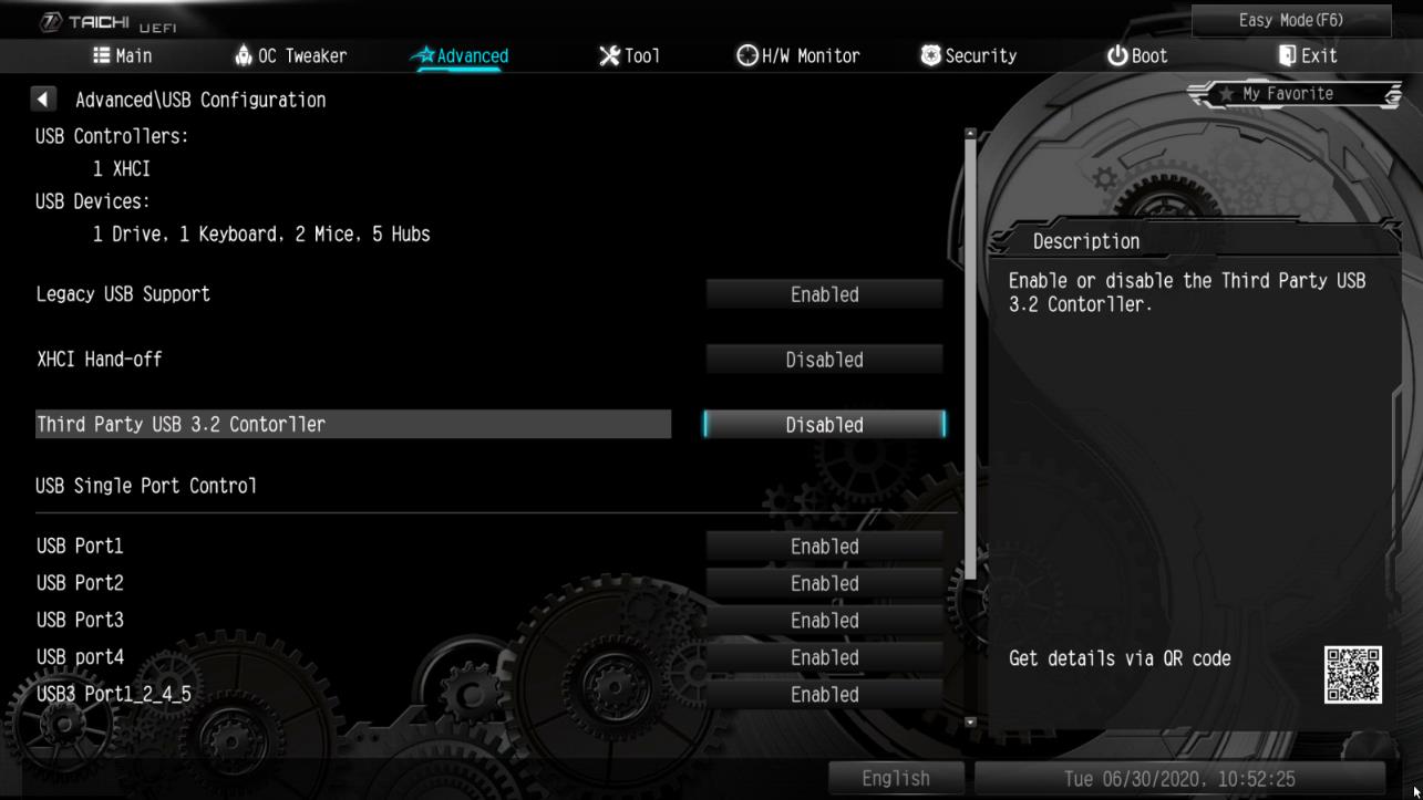
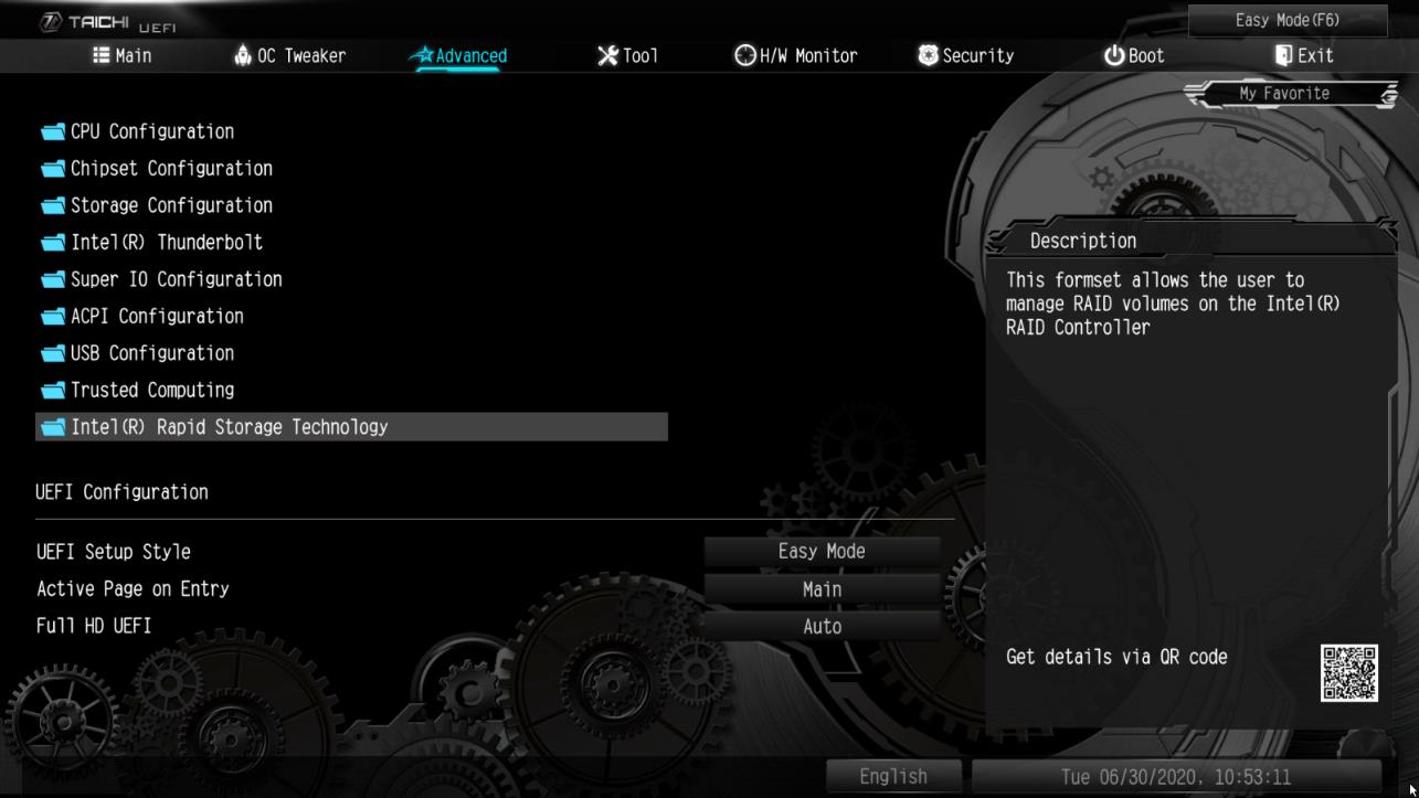
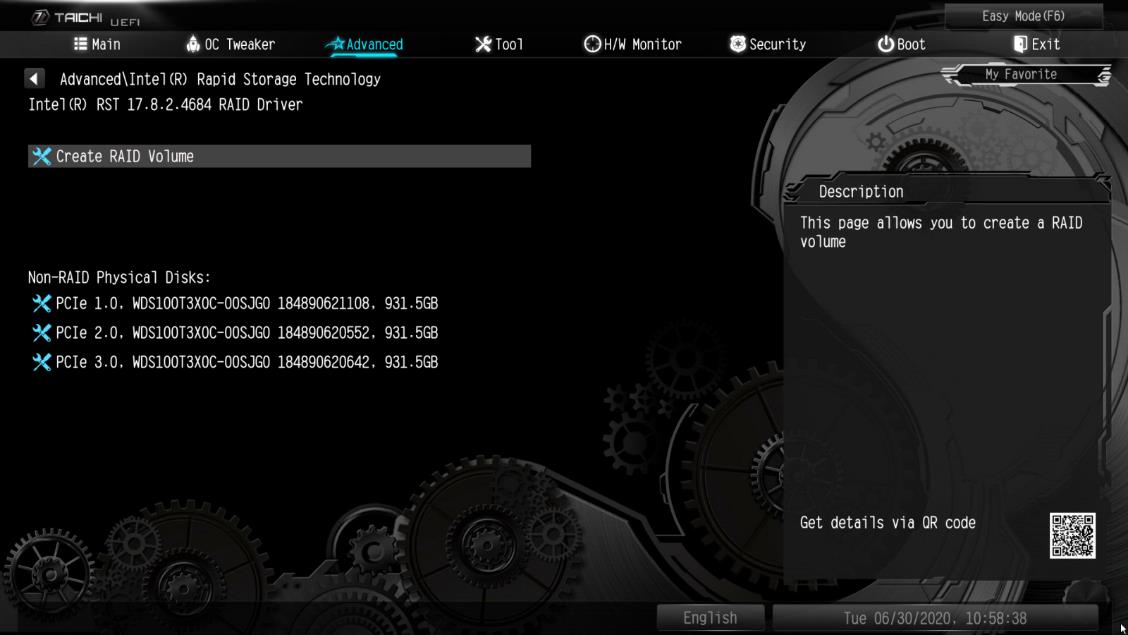
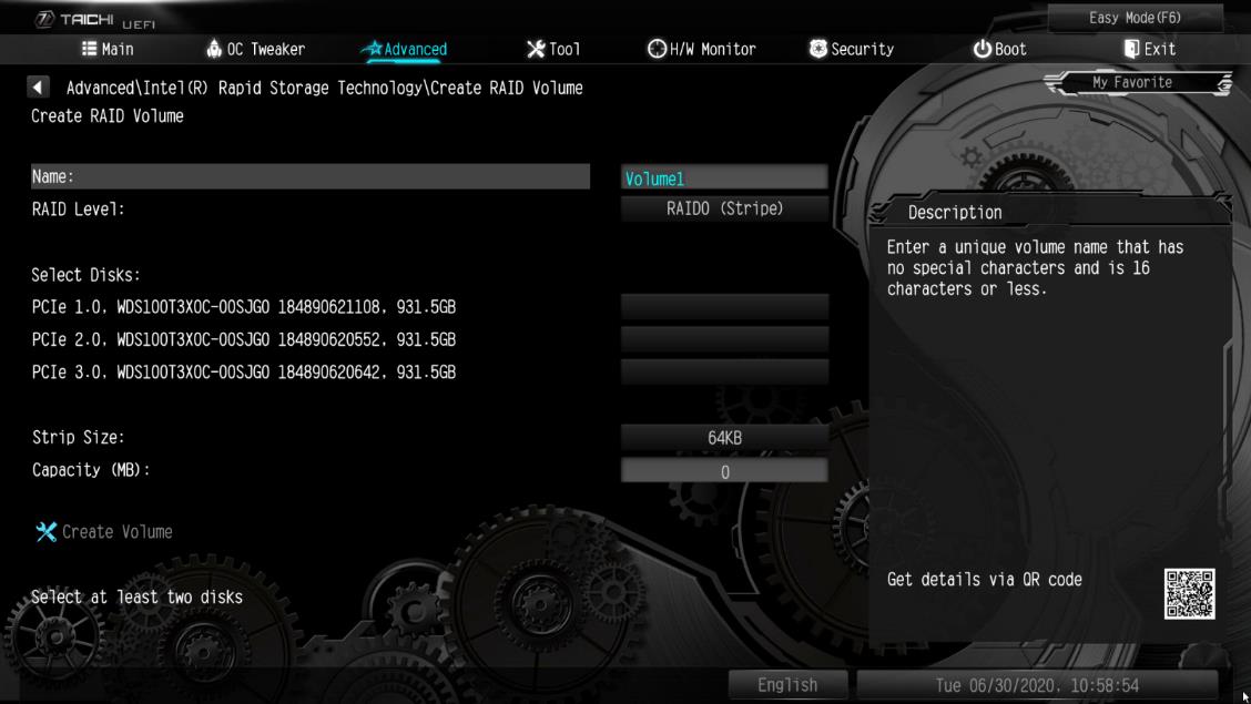
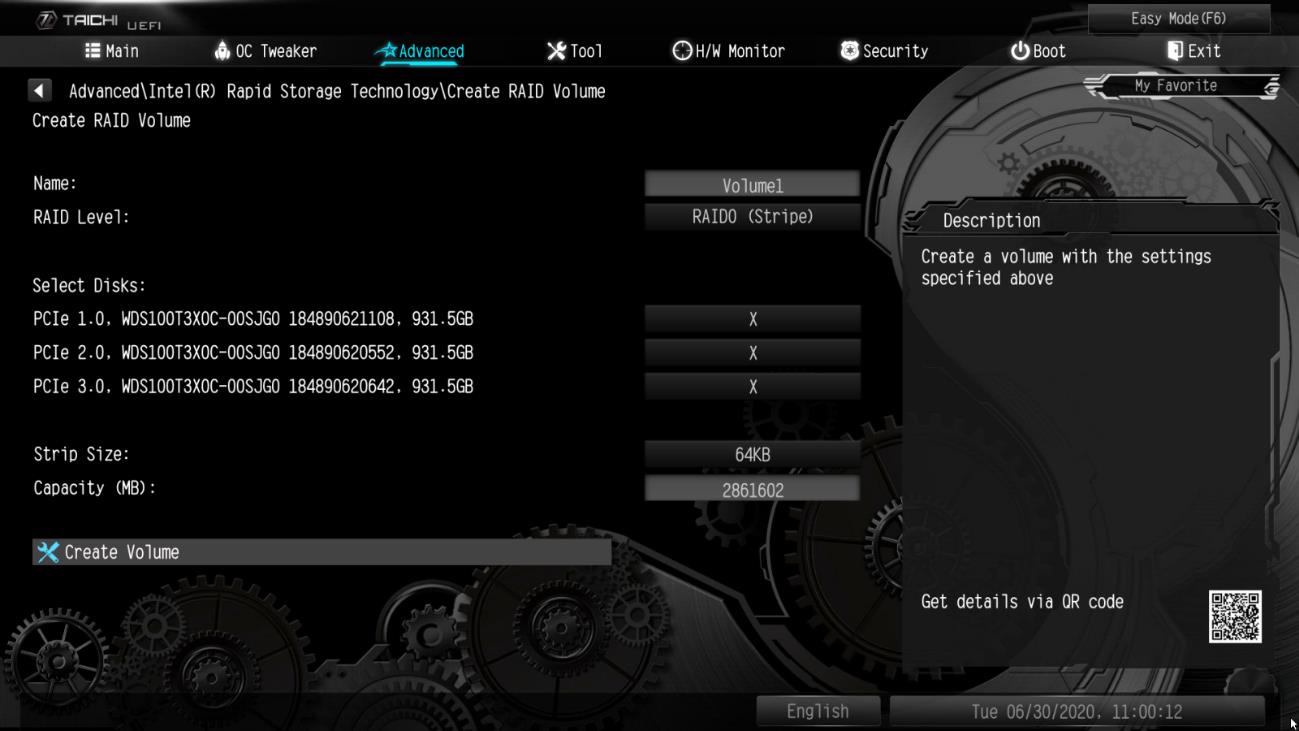
Wie kann ich den Steckplatz M2_3 und andere M.2-Steckplätze neu zuordnen, um ein PCIE-SSD-RAID zu konfigurieren?(6/1/2020)
A:Bitte stellen Sie sicher, dass Sie identische PCIE-SSDs verwenden, die vom gleichen Typ sind und die gleiche Kapazität besitzen. Führen Sie die folgenden Schritte aus, um die BIOS-Einstellungen zur Konfiguration des PCIe RAID anzupassen.
SCHRITT 1: Rufen Sie das UEFI-Setup auf, indem Sie während des Post-Bildschirms die Tasten oder drücken.
SCHRITT 2. Gehen Sie zu Advanced -> Storage Configuration und stellen Sie die SATA Mode Selection auf [RAID-Mode].
SCHRITT 3: Gehen Sie zu Boot -> CSM und stellen Sie Launch Storage OpROM policy auf [UEFI only].
SCHRITT 4. Stellen Sie die M.2-Steckplätze mit RST PCie Storage Remapping , in denen Sie PCIE-SSDs installiert haben, auf [Enabled]. Drücken Sie , um die Einstellungen zu speichern und das Setup zu verlassen.
SCHRITT 5. Gehen Sie zu Advanced -> USB Configuration und setzen Sie Third Party USB 3.2 Controller auf [Disabled]. Drücken Sie , um die Konfigurationsänderungen zu speichern und das Setup zu beenden.
Vorsicht: Nach der Deaktivierung von Third Party USB3.2 Controller ist der integrierte Typ-C-Port ausgeschaltet.
SCHRITT 6. Gehen Sie zu Intel(R) Rapid Storage Technology auf der Seite Advanced.
Schritt 7: Wählen Sie die Option Create RAID Volume und drücken Sie .
SCHRITT 8. Geben Sie eine Datenträger-Bezeichnung ein und drücken Sie , oder drücken Sie einfach , um die Vorgabe zu akzeptieren.
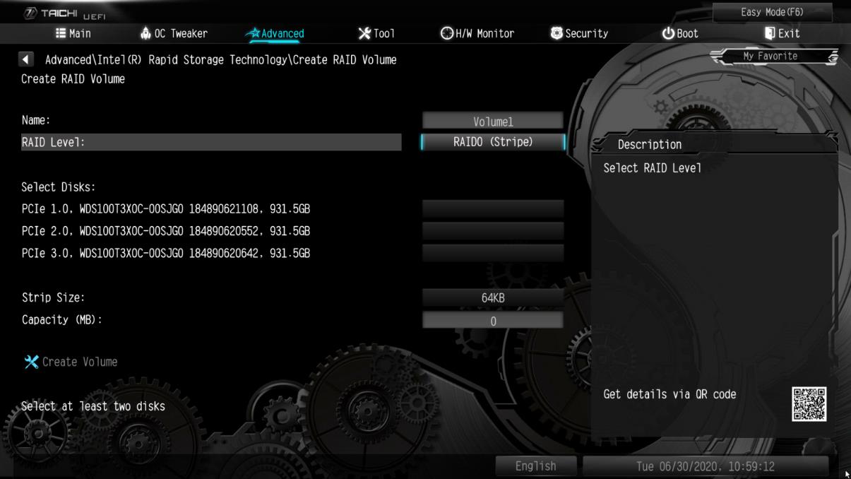
SCHRITT 9. Wählen Sie den gewünschten RAID-Level und drücken Sie .
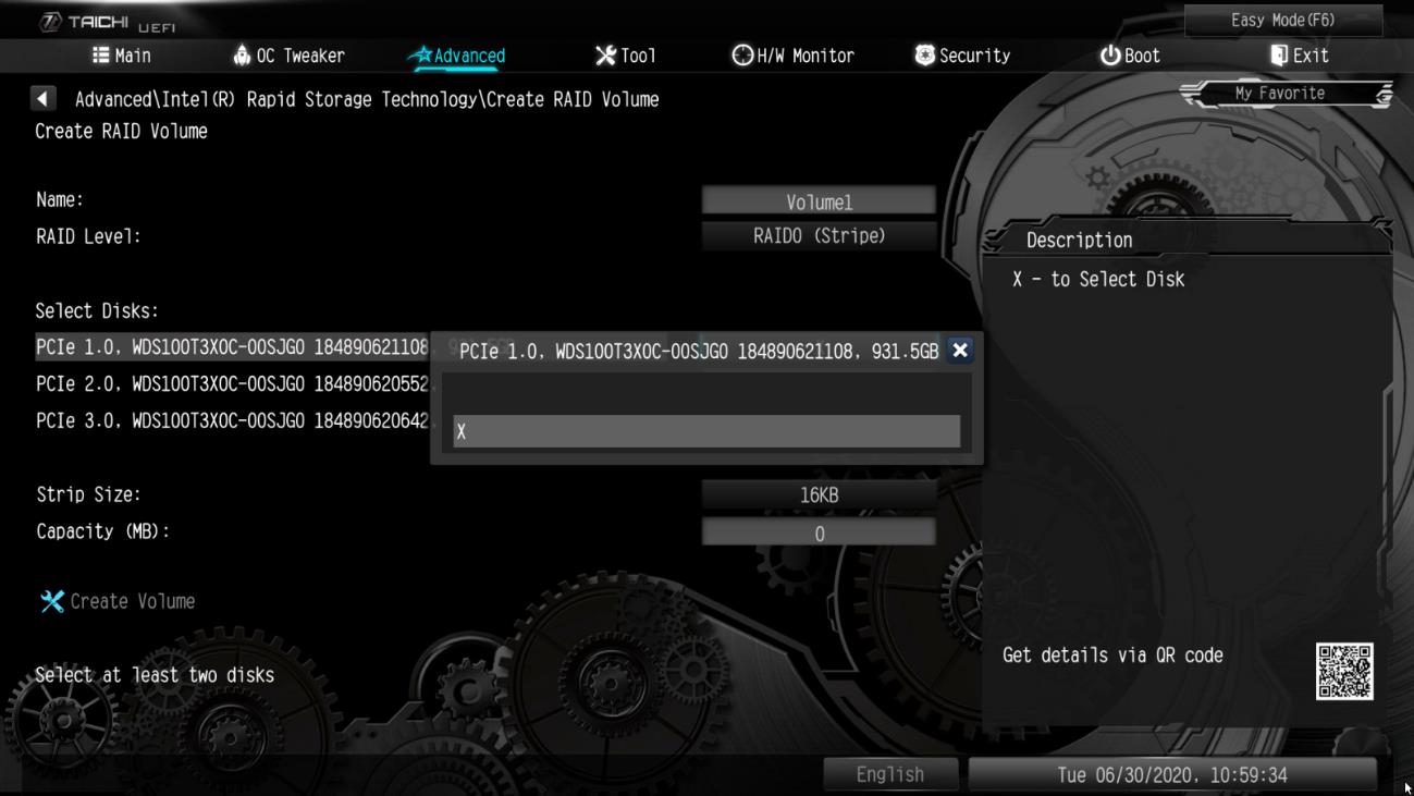
SCHRITT 10. Wählen Sie die Datenträger aus, die Sie in das RAID-Array einbauen möchten und drücken Sie .
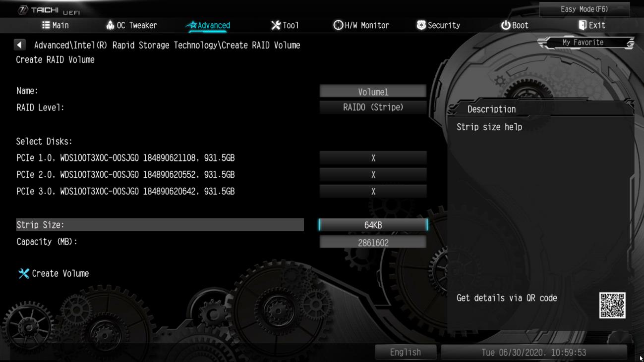
SCHRITT 11. Wählen Sie eine Stripe-Größe für das RAID-Array und drücken Sie .
SCHRITT 12. Wählen Sie Create Volume und drücken Sie , um das RAID-Arrays zu erzeugen.
Q (Q&A-145|479):
Ich habe eine Grafikkarte in meinem System installiert, aber der Monitor zeigt kein Signal an. Wie sollte ich vorgehen?(3/1/2019)
A:Bitte beachten Sie die folgenden Vorschläge, um Ihr System zu überprüfen.
1. Entfernen Sie die Grafikkarte und prüfen Sie, ob das System mit dem Onboard-Grafikausgang ein Signal an den Bildschirm schickt. Falls nicht, wird das Problem womöglich von anderen Geräten als der Grafikkarte ausgelöst.
2. Überprüfern Sie die Kabelverbindung zwischen der Grafikkarte und dem Monitor.
3. Stellen Sie sicher, dass das PCIe-Stromkabel korrekt mit der Grafikkarte verbunden ist.
4. Vergewissern Sie sich, dass die Eingangssignaleinstellung des Monitors für den Grafikausgang (DVI, HDMI, DP...) richtig konfiguriert ist.
5. Wenn Ihr Mainboard mehr als einen PCIe-Slot unterstützt, installieren Sie die Grafikkarte in einem anderen PCIe-Slot und versuchen Sie es erneut.
Q (Q&A-143|471):
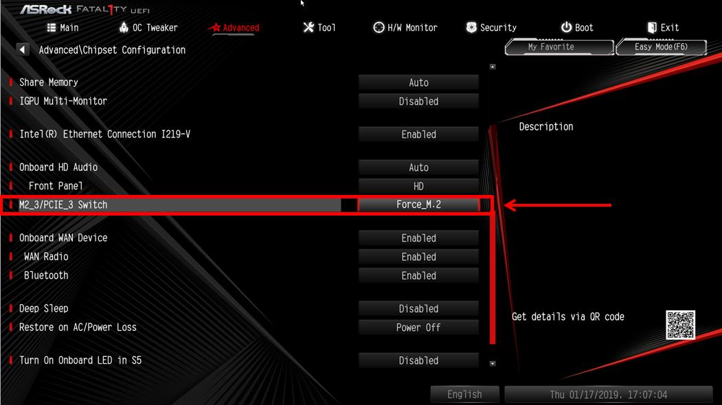
Wie aktiviere ich das WLAN mit der Karte AC 8260 auf einem Mainboard der H370-Plattform?(1/1/2019)
A:Um das WLAN mit AC 8260 ans Laufen zu bringen, müssen Sie die folgenden Einstellungen im BIOS vornehmen:
Setzen Sie die Einstellung für M2_3/PCIE_3 Switch auf Force_M.2. Sie finden die Einstellung unter dem Pfad Advanced\Chipset Configuration.
Drücken Sie nach der Änderung die Taste "F10”, um die neuen Einstellungen zu speichern.
Q (Q&A-138|462):
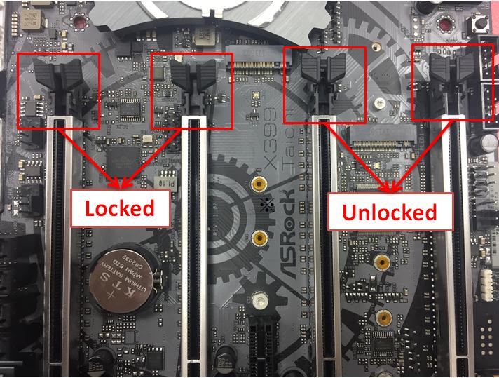
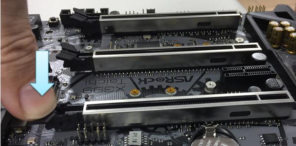
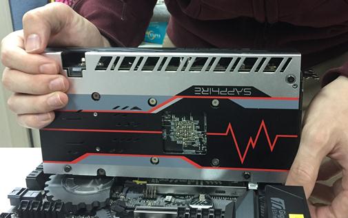
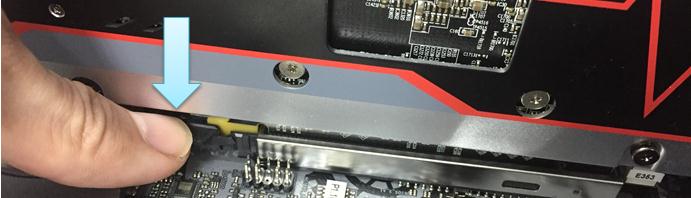
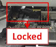
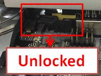
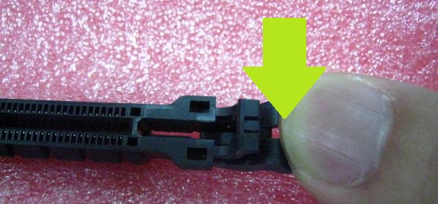
Ich habe bereits einige Kraft aufgewendet, um die PCIE-Grafikkarte auszubauen, bekomme Sie aber nicht aus dem Slot. Wie entferne ich die Karte bei der 300er-Serie richtig?
(2/1/2018)
A:Wenn Sie Schwierigkeiten haben, eine PCIE-Karte richtig zu installieren oder zu entfernen, befolgen Sie bitte die folgenden Schritte für eine sichere Installation/Deinstallation:
Schritt 1: Fahren Sie bitte das System herunter und trennen Sie die Stromversorgung.
Schritt 2: Lokalisieren Sie den Schließmechanismus des PCIE-Slots.
Schritt 3: Drücken Sie den Schließmechanismus sanft mit einem Finger herunter, bevor Sie eine PCIE-Karte installieren.
Schritt 4: Setzen Sie die PCIE-Karte mit zwei Händen über die gesamte Länge des PCIE-Slots ein.
Schritt 5: Drücken Sie den Schließmechanismus sanft mit einem Finger nach unten, um diesen zu entsperren und eine PCIE-Karte zu entfernen.
Schritt 6: Entfernen Sie langsam die Karte, während Sie diese mit beiden Händen fixieren.
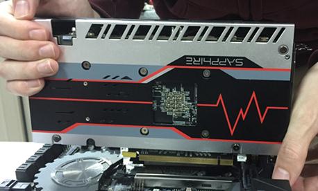
Q (Q&A-137|458):
Nach dem Update auf Windows 10 RS3 mit einem H81 Pro BTC(R2.0) zeigt der VGA-Treiber den Fehlercode "12” an. Wie löse ich das Problem?(12/1/2017)
Q (Q&A-136|456):
Ich möchte ein Mining-System auf Basis des H81 Pro BTC bauen. Muss ich die Buchse für den PCIe- Stromanschluss mit dem Netzteil verbinden?(11/1/2017)
A:Ja, es ist notwendig, dass Sie die Buchse für den PCIe-Stromanschluss mit dem Netzteil verbinden.
Stellen Sie bitte sicher, dass alle Stromanschlüsse vom gleichen Netzteil versorgt werden.
Nr.
Beschreibung
4
ATX-12-V-Stromanschluss (ATX12V1)
7
ATX-Mainboard-Stecker (ATXPWR1)
18
PCIe-Stromanschluss (PCIE_PWR2)
24
PCIe-Stromanschluss (PCIE_PWR1)
Q (Q&A-135|453):
Nein. Ryzen Master und A-Tuning sind nicht kombinierbar und können nicht zeitgleich genutzt werden.(10/1/2017)
A:Die X299-Plattform verfügt über keinen spezifischen Slot für die Thunderbolt-AIC-Karte.
Die Thunderbolt-AIC-Karte ist mit allen an der CPU angebundenen Slots kompatibel.
Wenn der PCIe-Slot aktiviert ist (in Abhängigkeit von der CPU), wird Thunderbolt automatisch vom Betriebssystem erkannt.
Beachten Sie bitte die folgenden PCIe-Lane-Konfigurationen auf Basis der CPU.
Bei der Installation einer CPU mit 44 Lanes laufen die Slots PCIE1/PCIE2/PCIE3/PCIE5 in den Modi x16/x8/x16/x0 oder x8/x8/x16/x8.
Sie können die Thunderbolt-Karte somit in den Slots PCIE1/PCIE2/PCIE3/PCIE5 nutzen.
Bei der Installation einer CPU mit 28 Lanes laufen die Slots PCIE1/PCIE2/PCIE3/PCIE5 in den Modi x16/x0/x8/x0 oder x8/x0/x8/x8.
Sie können die Thunderbolt-Karte somit in den Slots PCIE1/ PCIE3/PCIE5 nutzen.
Bei der Installation einer CPU mit 16 Lanes laufen die Slots PCIE1/PCIE2/PCIE3/PCIE5 in den Modi x16/x0/x0/x0 oder x8/x0/x4/x0.
Sie können die Thunderbolt-Karte somit in den Slots PCIE1/ PCIE3 nutzen.
Q (Q&A-135|454):
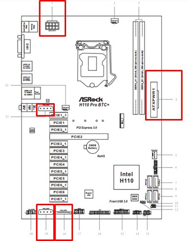
Wie schließe ich die Stromversorgung an das H110 Pro BTC+ an, wen ich in meinem Mining-Systeme zwei Netzteile nutze?(10/1/2017)
A:Wenn Sie zwei Netzteile für Ihr Mining-System verwenden, müssen die Stromanschlüsse des H110 Pro BTC+ von dem gleichen Netzteil versorgt werden.
Stellen Sie dafür bitte sicher, dass alle angeschlossenen Stromstecker (4-Pin, 24-Pin, SATA und PCIe) mit dem gleichen Netzteil verbunden sind.
Nr.
Beschreibung
1
ATX-12V-Stromanschluss (ATX12V1)
4
ATX-Stromanschluss (ATXPWR1)
18
SATA-Stromanschluss (SATA_POW1)
19
PCIe-Stromanschluss (PCIE_PWR2)
21
PCIe-Stromanschluss (PCIE_PWR1)
Q (Q&A-134|448):
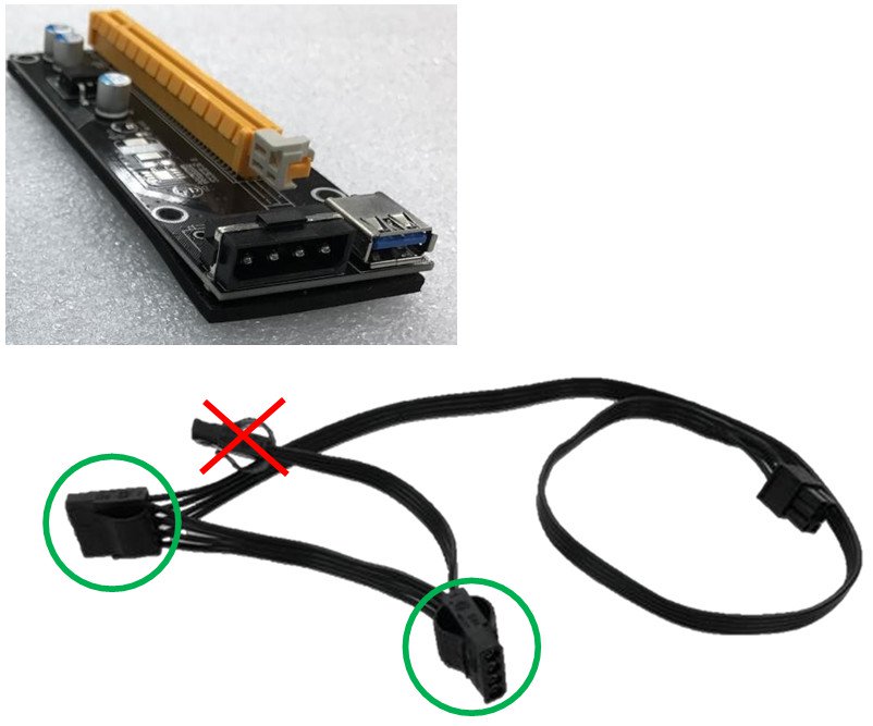
Das System erkennt eine meiner Grafikkarten nicht. Was soll ich machen?(9/1/2017)
A:Wenn eine Grafikkarte vom System nicht erkannt wird, muss das nicht notwendigerweise nur mit dem Mainboard zusammenhängen, sondern kann auch an anderen Komponenten liegen. Die Riser-Karten, die Stromversorgung, die Grafikkarten selber und sogar das Betriebssystem sind alles Schlüsselkomponenten. Halten Sie sich daher bitte an die drei folgende Punkte, um das System zu prüfen.
(A) Die PCIe-Riser-Karte
1. Bitte überprüfen Sie gründlich, ob die Grafikkarte korrekt in der Riser-Karte installiert wurde. Sie können die Grafikkarte auch aus der Riser-Karte entfernen und erneut einsetzen.
2. Wir empfehlen für das Mining-System die Nutzung von PCIe-Riser-Karten mit einer 6-Pin-Stromversorgung.
3. Wenn Sie eine PCIe-Riser-Karte mit Molex-Anschluss verwenden, nutzen Sie bitte maximal zwei Molex-Stecker pro Stromkabel für die Riser-Karten, nicht mehr.
(B) Die Stromversorgung
Wenn Sie 13 Grafikkarten, oder ähnliche viele, nutzen, werden Sie vermutlich zwei Netzteile verwenden. In einem Mining-System mit mehreren Netzteilen, müssen einige Dinge beachtet werden. Das erste Netzteil muss mit dem Mainboard (12 V, 5 V und 3,3 V) und einigen der Grafikkarten (12 V) verbunden sein. Das zweite Netzteil sollte ausschließlich für die weiteren Grafikkarten (12 V) verwendet werden. Da das zweite Netzteil somit nur auf der 12-V-Schiene belastet wird, kann es zu einem Ungleichgewicht bei der Stromversorgung kommen.
Hersteller von Netzteilen empfehlen die Verwendung von nur einem Netzteil pro System.
(C) Die Grafikkarten
1. Ein Single-GPU-System verbraucht für gewöhnlich etwa 200 Watt. Ein Multi-GPU-System benötigt ein Vielfaches davon. Prüfen Sie bitte gründlich, ob genügend Leistung für das gesamte System zur Verfügung steht.
2. Bitte installieren Sie Grafikkarten einzeln und überprüfen Sie, ob diese im Gerätemanager angezeigt werden.
Wenn dies nicht der Fall ist, starten Sie das System neu, und prüfen Sie, ob das System die Grafikkarte nun erkennt.
3. Wird die Grafikkarte weiterhin nicht erkannt, reinigen Sie bitte die Goldkontakte der Grafikkarte mit einem Radiergummi und installieren Sie die Karte erneut.
Q (Q&A-128|421):
Welche M.2 Spezifikation unterstützten unsere AM4 Mainboards? Wird ein SATA Anschluss gemeinsam genutzt? Wenn ja, welcher?(3/1/2017)
A:Folgende Tabelle zeigt die M.2 Spezifikation und welchen geteilten SATA Port genutzt wird:
Model
M.2 Unterstützung PCIE/SATA
Wird M.2 mit SATA Port geteilt?
Fatal1ty X370 Professional Gaming
M2_1 (PCIE/SATA)
NO
X370 Taichi
M2_1 (PCIE/SATA)
NO
X370 Killer SLI/ac
M2_1, M2_2 (PCIE/SATA)
NO
X370 Killer SLI
M2_1, M2_2 (PCIE/SATA)
NO
Fatal1ty X370 Gaming K4
M2_1, M2_2 (PCIE/SATA)
NO
Fatal1ty AB350 Gaming K4
M2_1(PCIE), M2_2(SATA)
M2_1(share with PCIE4), M2_2(share with SATA3_3)
AB350 Pro4
M2_1(PCIE), M2_2(SATA)
M2_1(share with PCIE4), M2_2(share with SATA3_3)
AB350M Pro4
M2_1(PCIE), M2_2(SATA)
M2_2(share with SATA3_3)
AB350M-HDV
M2_1 (PCIE/SATA)
NO
AB350M
M2_1 (PCIE/SATA)
NO
Q (Q&A-125|413):
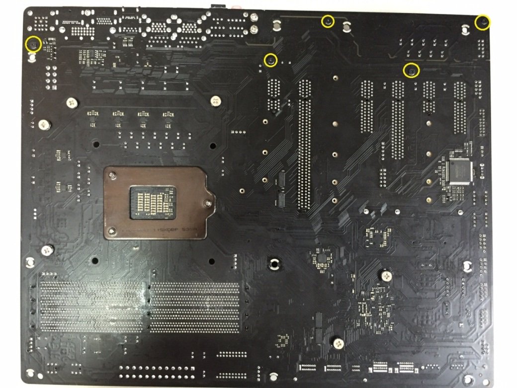
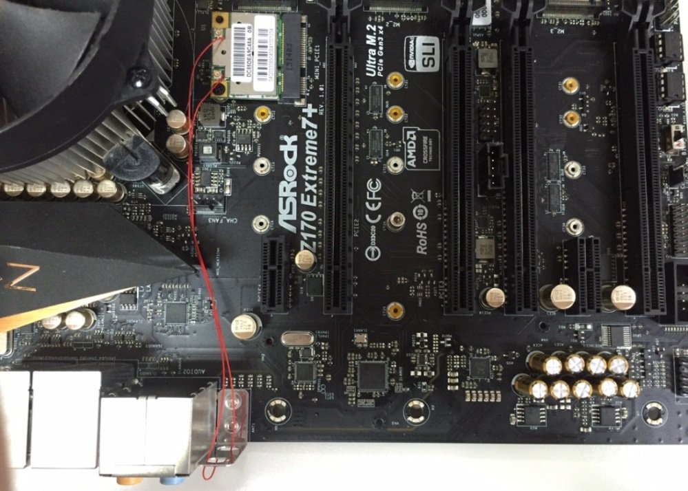
Wie schließe ich die Antennen an der Karte an, wenn ich eine WLAN-Karte für Mini-PCIe mit einem Z170 Extreme7+ nutzen möchte?(6/1/2016)
A:Wenn die Verbindungskabel zwischen den WLAN-Antennen und der WLAN-Karte für den Mini-PCIe-Slot kürzer sind als 26 Zentimeter, befolgen Sie bitte die folgenden Schritte:
Schritt 1: Lösen Sie die fünf Schrauben auf der Rückseite des Z170 Extreme 7+, die auf folgendem Bild mit den gelben Kreisen markiert sind. Entfernen Sie dann das I/O-Schild.
Schritt 2: Nutzen Sie das rote Kabel, um die WLAN-Karte für Mini-PCIe mit den Antennenanschlüssen am I/O-Port zu verbinden.
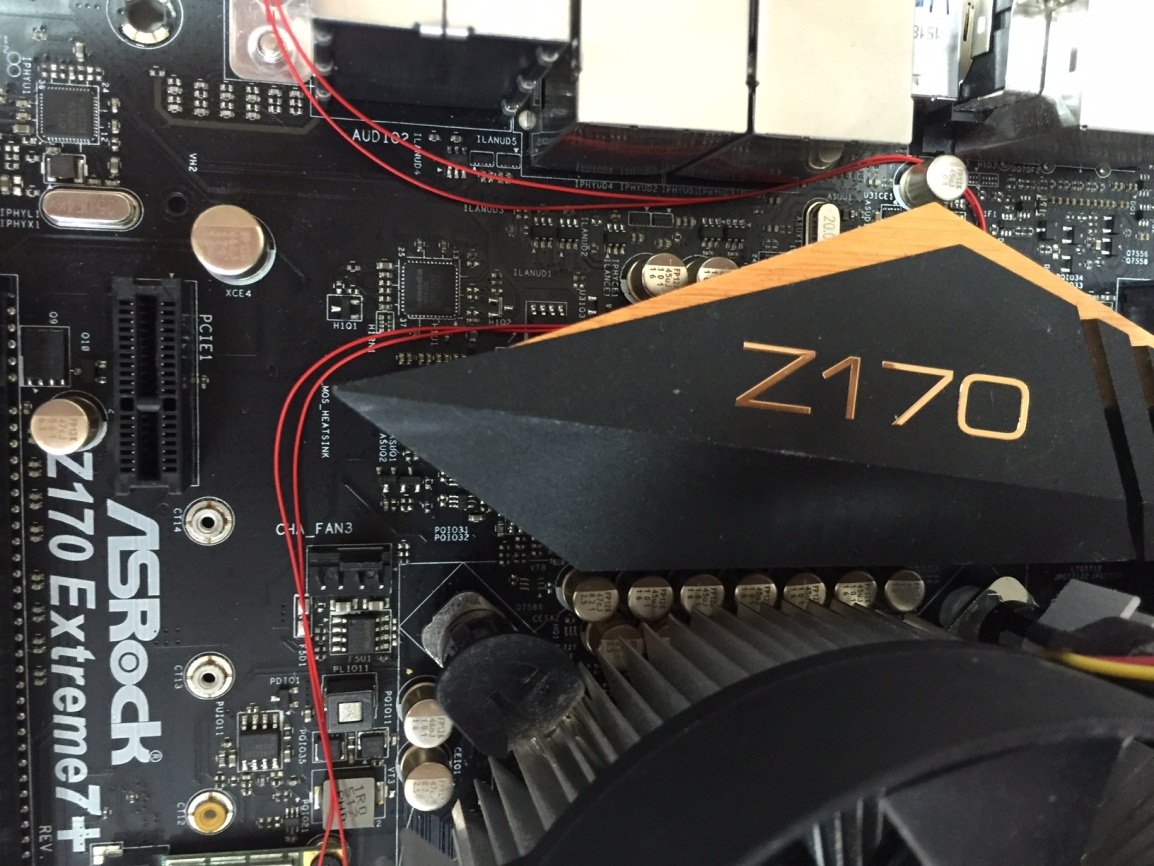
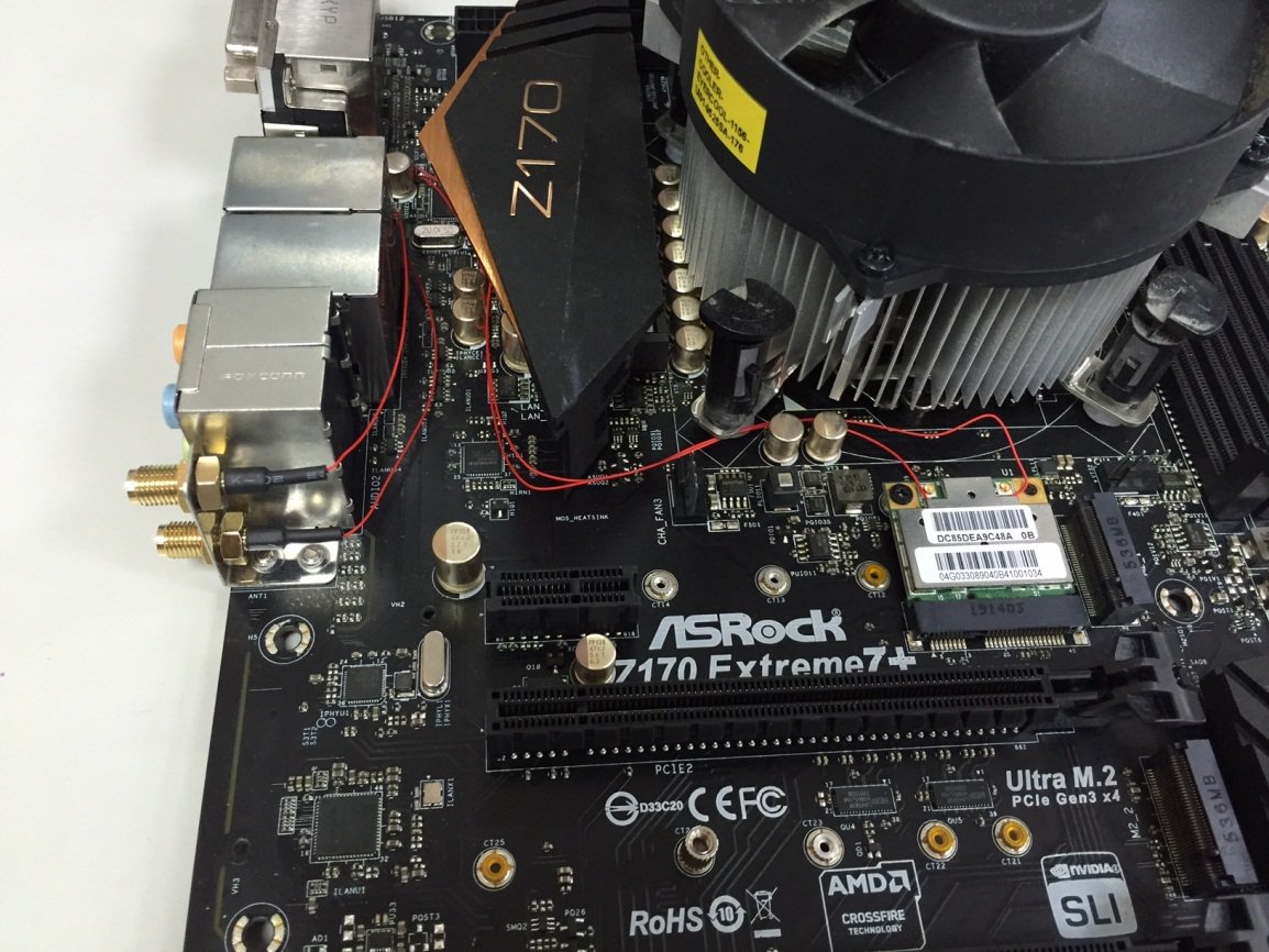
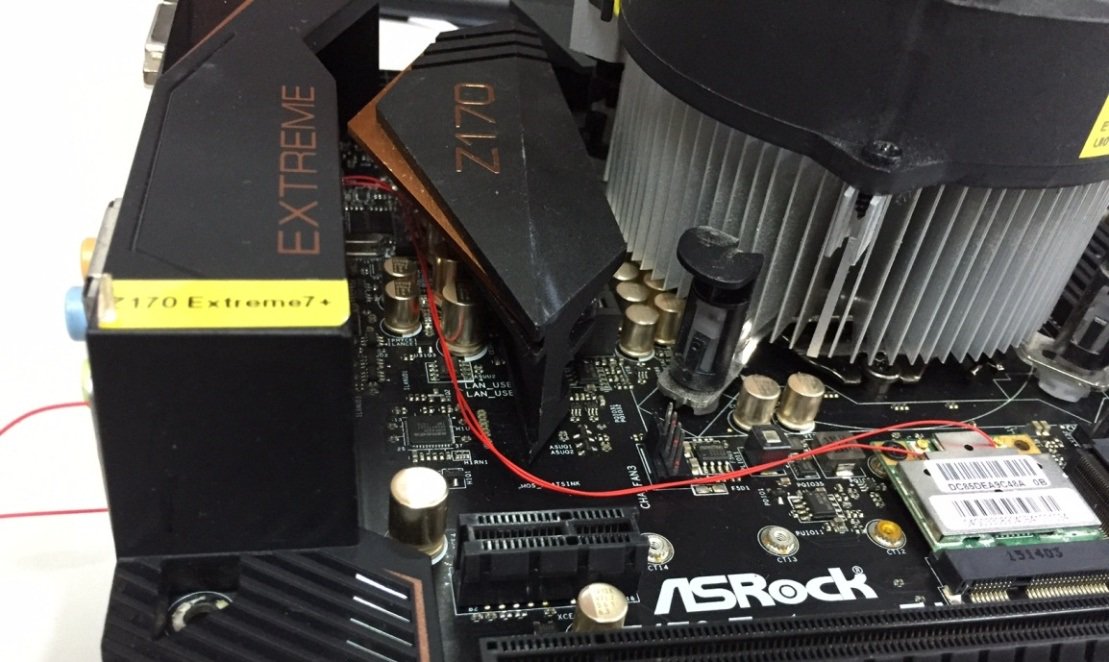
Wenn die Verbindungskabel zwischen den WLAN-Antennen und der WLAN-Karte für den Mini-PCIe-Slot länger sind als 26 Zentimeter, befolgen Sie bitte die folgenden Schritte:
Schritt 1: Lösen Sie die fünf Schrauben auf der Rückseite des Z170 Extreme 7+, die auf folgendem Bild mit den gelben Kreisen markiert sind. Entfernen Sie dann das I/O-Schild.
Schritt 2: Verlegen Sie das rote Kabel, wie auf dem folgendem Foto zu sehen ist, um die WLAN-Karte für Mini-PCIe mit den Antennenanschlüssen am I/O-Port zu verbinden.
Schritt 3: Installieren Sie das I/O-Schild vom Z170 Extreme7+ wieder, wie auf dem folgenden Foto.
Q (Q&A-116|387):
Nach dem Einbau von zwei Grafikkarten vom Typ R9 295x2 in meine X99-Plattform scheitert der Bootvorgang des Systems. Wie löse ich das Problem?(3/1/2015)
A:Bitte beachten Sie die folgenden Schritte um das BIOS zu updaten. Sie finden das BIOS auf der ASRock-Homepage.
Modell
BIOS-Version
X99 Extreme3
P1.80
X99 Extreme4
P1.80
X99 Extreme6
P1.80
X99 Extreme6/ac
P1.60
X99 Extreme11
P1.10
X99 OC Formula
P1.80
X99 Professional
P1.60
X99 WS
P1.70
X99 WS-E
P1.20
X99 WS-E/10G
P1.20
X99M Extreme4
P1.70
X99M Killer
P1.80
X99X Killer
P1.80
Schritt 1. Bitte entfernen Sie alle nicht notwendigen PCI-E-Geräte, darunter auch eine der Grafikkarten vom Typ R9 295x2, so dass nur eine Grafikkarte für die Bildausgabe zuständig ist.
Schritt 2. Starten Sie das System und wechseln Sie ins BIOS.
Schritt 3. Laden Sie dort die Standardeinstellungen des BIOS (Default Settings) und speichern Sie die Änderung.
Schritt 4. Laden Sie erneut das BIOS und nutzen Sie die Option "Instant Flash" um das neueste BIOS zu installieren.
Schritt 5. Bauen Sie nach dem erfolgreichen BIOS-Update die zweite Grafikkarte vom Typ R9 295x2 wieder ein.
Q (Q&A-115|382):
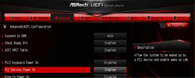
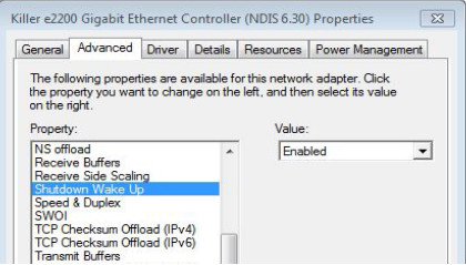
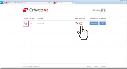
Ich habe versucht die "Wake On Internet Technology" von Orbweb mit meinem H87 Killer zu nutzen, aber ich konnte mein System nicht aufwecken, nachdem ich es via Remote in den Sleep-Modus versetzt habe. Was soll ich machen?(12/1/2014)
2.Dienstalieren Sie den alten Netzwerktreiber und installieren Sie anschließend den neuen Treiber.
3.Stellen Sie sicher, dass die Option "PCI Devices Power On" im UEFI unter Advanced > ACPI Configuration aktiviert ist.
(*The UEFI screen is for reference only. The actual screen may differ by model.)
4. Stellen Sie sicher, dass die Optionen "Wake-On-LAN herunterfahren" ("Shutdown Wake Up") und "Sicheres Wake-On-Internet" ("SWOI") aktiviert sind unter: Gerätemanager > Netzwerkadapter > Eigenschaften vom Killer e2200 Gigabit Ethernet Controller (NDIS 6.30) > Erweitert.
5. Nutzen Sie Orbweb um Ihr System mittels Remote zu kontrollieren, in den Sleep-Modus zu versetzen und aufzuwecken.
Q (Q&A-111|361):
Wie aktiviere ich das Feature 'Dual Graphics' bei einer AMD-Plattform?(3/1/2014)
A:Schritt 1:
Bitte stellen Sie sicher, dass sie die neueste BIOS-Version installiert haben und im UEFI bei der Einstellung "Dual Graphics" die Standardoption [Auto] eingestellt haben.
Download-Link für das BIOS: https://www.asrock.com/support/download.asp
Schritt 2:
Installieren Sie eine Grafikkarte vom Typ AMD Radeon im PCIe-Slot.
Schritt 3:
Verbinden Sie das Monitorkabel mit dem onboard verfügbaren VGA-Ausgang. Bitte beachten Sie, dass der aktuelle Grafiktreiber und das VBIOS die Grafikausgabe mit aktivierter "Dual Graphics"-Funktion nur über den Onboard-Anschluss zulässt.
In Bezug auf kommende Updates überprüfen Sie bitte unsere Webseite auf neue Informationen.
Schritt 4:
Booten Sie ins Betriebssystem.
Deinstallieren Sie den AMD-Treiber, sollte dieser installiert sein.
Schritt 5:
Installieren Sie den Treiber für die Onboard-Grafikkarte und die diskrete Grafikkarte von der Support-CD.
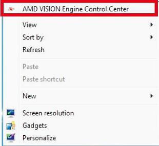
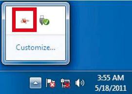
Schritt 6:
Starten Sie den Computer neu. Führen Sie einen Rechtsklick auf dem Desktop aus und klicken Sie auf den Eintrag "AMD VISION Engine Control Center" um das Konfigurationstool zu starten.
Schritt 7:
Sie können auch in der Taskbar auf den Eintrag "AMD VISION Engine Control Center" klicken um das Konfigurationstool zu starten.
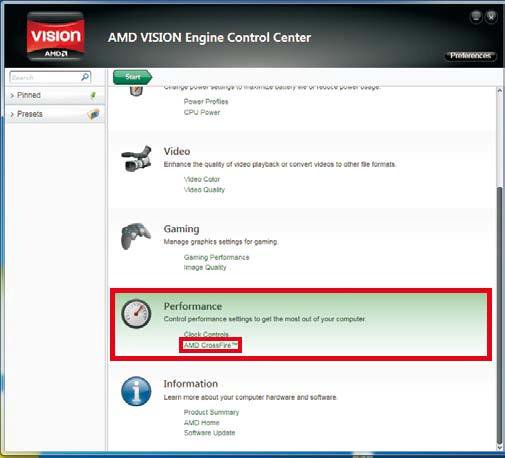
Schritt 8:
Im AMD VISION Engine Control Center wählen Sie bitte den Punkt "Performance" und klicken dort auf "AMD CrossFire™".
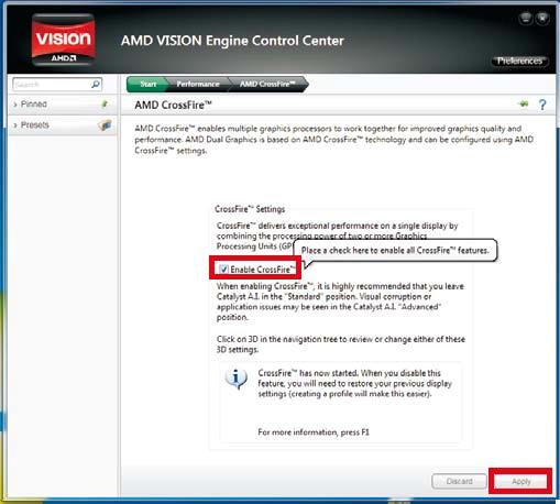
Schritt 9:
Klicken Sie auf "Enable CrossFire™" und anschließend auf "Apply" um die Einstellungen zu speichern.
Schritt 10:
Starten Sie das System neu. Nun sollten Sie die 'Dual Graphics'-Funktion nutzen können.
Q (Q&A-102|334):
Was ist Dr. Debug und wie helfen mir die Codes?(2/1/2013)
A:Die angezeigten Codes sind Statuscodes. Es ist normal, dass während des POST mehrere Codes angezeigt werden. Wenn das System immer bei einem bestimmten Code einfriert, kann dieser Code zur Fehlerbehebung verwendet werden. In der folgenden Tabelle finden Sie die Codes und die vorgeschlagenen Maßnahmen.
Code
Beschreibung
FF, 00 - 19 D0 - D3
Bitte überprüfen Sie, ob die CPU korrekt installiert ist und löschen Sie dann das CMOS.
31 - 3B 51 - 55
Problem im Zusammenhang mit CPU und Speicher. Bitte löschen Sie das CMOS. Installieren Sie die CPU und den Speicher neu.
D4 - D5
PCI-Ressourcenzuweisungsfehler. Keine Ressourcen mehr.
D6 92 - 97
Die Grafikkarte oder iGPU konnte nicht erkannt werden. Bitte löschen Sie das CMOS und versuchen Sie, die Grafikkarte neu zu installieren. Wenn das Problem weiterhin besteht, versuchen Sie bitte, die Grafikkarte in anderen Steckplätzen zu installieren oder andere Grafikkarten auszuprobieren.
D7
Tastatur und Maus konnten nicht erkannt werden. Versuchen Sie bitte, Tastatur und Maus neu zu installieren.
D8
Ungültiges Passwort
9A - 9D
Problem im Zusammenhang mit USB-Geräten. Versuchen Sie bitte, alle USB-Geräte zu entfernen.
E8 - EB
S3 Wiederaufnahme fehlgeschlagen (S3=Schlafen)
03
System tritt in den S3 Zustand ein (S3=Schlafen)
04
System tritt in den S4 Zustand ein (S4=Hibernieren)
05
System tritt in den S5 Zustand ein (S5=Sanftes Ausschalten)
30
System wacht aus S3 Zustand auf (S3=Schlafen)
40
System wacht aus S4 Zustand auf (S4=Hibernieren)
AA
System tritt in OS ein
Q (Q&A-98|321):
Welche Mini-PCIE-Geräte werden vom Z77 Extreme6 unterstützt?(10/1/2012)
A:Es werden drei verschiedene Arten von Geräten für das Mini-PCIE-Interface unterstützt.
1. Mini-PCIE
2. mSATA
3. USB
Das Z77 Extreme6 unterstützt nur das Mini-PCIE-Interface, darunter mini-PCIE-WLAN oder mini-PCIE-Netzwerk.
Q (Q&A-90|300):
Ich möchte die SSD OCZ RevoDrive für den PCI-Express-Slot auf einer X58-Plattform verwenden. Welche Einstellungen müssen im BIOS vorgenommen werden?(12/1/2011)
A:Bitte updaten Sie Ihr BIOS auf die aktuellste Version und stellen Sie sicher, dass die BIOS-Einstellung [PCIE Max Payload Size] auf [128B] gesetzt ist.
Sie finden die Option im BIOS unter [Advanced] -> [PCIE Max Payload Size].
BIOS Download-Link: https://www.asrock.com/support/download.de.asp
Q (Q&A-86|289):
I install Microsoft® Windows® OS in GPT mode and Ubuntu in MBR mode with two different HDD, and I cannot boot into Microsoft® Windows® OS, how to solve that?(6/1/2011)
A:Please install OS both in GPT or MBR mode.
Both in GPT mode, please refer below steps:
1. Boot into BIOS→[Boot]→[PCI ROM Priority]→choose [EFI Compatible ROM], then press "F10" to save changes and exit.
2. Then press "F11" when booting up and choose "UEFI:[your ODD name]" to install OS.
Both in MBR mode, please refer below step:
Please press "F11" when booting up and choose "AHCI/SATA:[your ODD name]" to install OS.
Q (Q&A-81|274):
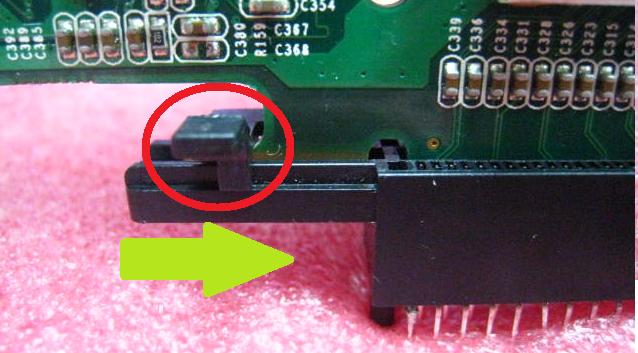
Wie verwende ich den PCIE-Verschluss meines Mainboards?(12/30/2010)
A:Aktuell gibt es folgende Verschlusstypen für PCIE: Typ 1:
1. Bevor die Grafikkartte installiert wird, schieben Sie den Verschluss in horizontaler Richtung zur rechten Seite um die Sicherung zu lösen.
2. Schieben Sie den Verschluss nach der Installation der Grafikkarte wieder zurück.
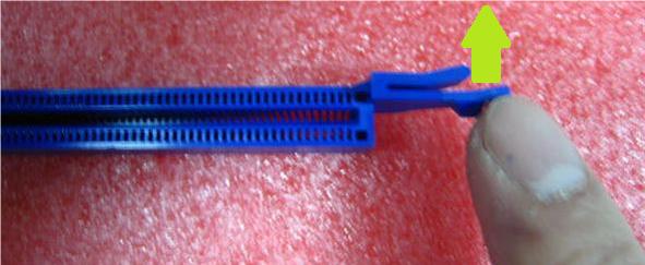
Typ 2:
1. Installieren Sie die Grafikkarte vertikal im PCIE-Slot.
2. Um die Grafikkarte zu entfernen, drücken Sie den Verschluss wie auf dem folgenden Bild beschrieben nach hinten.
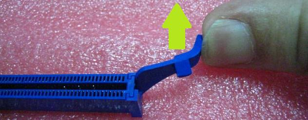
Typ 3:
1. Installieren Sie die Grafikkarte vertikal im PCIE-Slot.
2. Um die Grafikkarte zu entfernen, drücken Sie den Verschluss wie auf dem folgenden Bild beschrieben nach hinten.
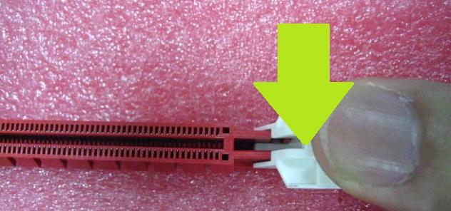
Typ 4:
1. Installieren Sie die Grafikkarte vertikal im PCIE-Slot.
2. Um die Grafikkarte zu entfernen, drücken Sie den Verschluss wie auf dem folgenden Bild beschrieben nach unten.
Typ 5:
1. Installieren Sie die Grafikkarte vertikal im PCIE-Slot.
2. Um die Grafikkarte zu entfernen, drücken Sie den Verschluss wie auf dem folgenden Bild beschrieben nach unten.
Typ 6:
1. Installieren Sie die Grafikkarte vertikal im PCIE-Slot.
2. Um die Grafikkarte zu entfernen, ziehen Sie die Karte vertikal wieder heraus.
Notiz: Wenn der Verschluss nicht verfügbar ist, wirkt sich das nicht auf die Qualität der Verbindung aus.
Q (Q&A-75|256):
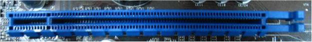
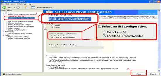
I have plug two NVIDIA® VGA cards on my motherboard but, I cannot find the Enable SLI option in NVIDIA® Control panel?(9/3/2009)
A:Following steps as below may help you to solve this issue.
1. If your motherboard has the SLI/XFire switch card, please put the SLI/XFire Switch card to 8x/8x, if there is no switch card on your motherboard, please skip this step.
2. Remove the graphics card from the PCI-E 1 slot.
3. Restart Windows.
4. Install the driver for the graphics card (again).
5. Put the VGA card back into the PCI-E 1 slot, and put the SLI bridge on.
6. Activate SLI function by NVIDIA® control panel ..
7. Or please download the latest VGA driver from NVIDIA® Web Site and try the new
driver. http://www.nvidia.com/Download/index.aspx?lang=en-us
Q (Q&A-70|245):
I install ATI 2xxx, 3xxx, 4xxx series PCIE VGA card on the motherboard. After installing all Windows® XP drivers from the motherboard, it still shows an unknown "audio device on the high definition audio bus." message under device manager. What could I try?(1/12/2009)
A:There is an integrated audio chip in the ATI 2xxx, 3xxx, 4xxxx series graphics cards.
Please install ATI HDMI audio driver.
http://ati.amd.com/support/drivers/xp/hdmiaudio-xp.html
Q (Q&A-67|237):
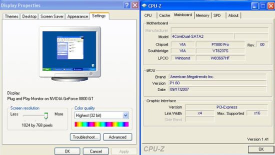
When I install a Terratec Cinergy C PCI TV card or Technisat Cablestar HD2 TV card on VIA® chipset based motherboards, such like 4CoreDual-SATA2 (PT880 series motherboards) or ALiveSATA2-GLAN, it always show "PCI IRQ routing table error" message after BIOS POST, or simply hang up during BIOS POST. Any way to fix the problem?(9/5/2008)
A:Due to compatibility issue of VIA® chipset with Terratec Cinergy C PCI TV card and Technisat Cablestar HD2 TV card.
We don't recommend using this kind of TV card on VIA® chipset motherboards. Sorry for your inconvenience.
Q (Q&A-65|231):
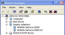
When installing NVIDIA GeForce 8400/8500 series PCIE VGA card on K10N78hSLI-WiFi / K10N78hSLI-1394 / K10N78hSLI-GLAN under Windows® XP/ XP 64-bit, I can not get full system memory. Besides, system shows two display adapters in the Device Manager. What can I do? (6/26/2008)
A:While system boot up, please press "F2" to enter BIOS set up screen. Please go into BIOS setup and set "Hybrid SLI" option to [Disabled] in BIOS>Advanced>Chipset Configuration.
Q (Q&A-59|214):
I use a NVIDIA® 8800GT PCIE VGA card on VIA® chipset motherboard. But I got black screen on the monitor. How do I solve it?(11/5/2007)
A:The NVIDIA® 8800GT PCIE VGA card is GEN2 mode VGA card. Unfortunately VIA® chipset does not support GEN2 mode VGA card. The only solution is to set 8800GT PCIE VGA card to GEN1 mode.
We have tested 8800GT PCIE VGA card. After flashing GEN1 mode BIOS for 8800GT, it works fine on VIA® chipset motherboard.
Please contact VGA card vender to get the VGA BIOS with GEN1 mode for your 8800GT PCIE VGA card.
Q (Q&A-57|207):
After installing ATI HDMI audio driver for my ATI HD 2xxx series PCIE card, I found the onboard sound will not work. How do I fix the problem?(9/10/2007)
A:Please kindly refer to below steps to check your system setting.
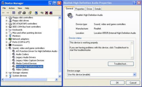
1.Please double check the onboard sound is working properly in Device Manager.
(If not, please reinstall Realtek HD Audio driver from Support CD.)
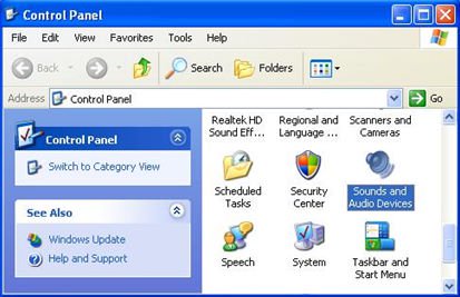
2.Enter the Sound setting in the Control Panel.
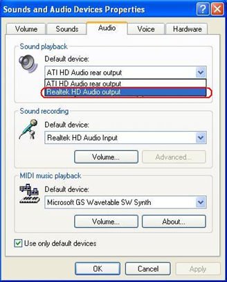
3.If the Default device of the Sound playback is "ATI HD Audio rear output", please change it to "Realtek HD Audio output".
4.Press "OK" to save setting.
Q (Q&A-56|205):
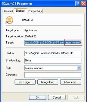
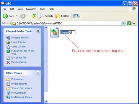
I am using the onboard VGA of A780FullDisplayPort or ATi Radeon HD 2xxx/3xxx series PCIE card. Every time I run the 3DMARK or PCMARK, it always freezes during the splash-screen. It does not work at all. How do I fix it?(8/3/2007)
A:This is a compatibility issue of ATi Radeon HD 2xxx/3xxx PCIE card and 3DMARK/ PCMARK program.
Futuremark provides 2 solutions for this issue as follows. Solution 1: Add the command line –nosysteminfo into the target of 3DMARK / PCMARK's shortcut. Solution 2: Rename the "Direcpll.dll" file to something else. (Found in C:\WINDOWS\system32\Futuremark\MSC\Direcpll.dll)
The link of Futuremark FAQ:
http://service.futuremark.com/support/search.jsp?categoryid=14&search=1
Q (Q&A-48|187):
I have 939Dual-SATA2 / 939Dual-VSTA / 939A8X-M / K8A8X-M / K8Upgrade-1689/K8Combo-Z motherboard. When using Nvidia 7600GS/6600LE/6800GS/7800GS "AGP" card, I am not able to install the VGA card driver. How can I solve this?(11/19/2006)
A:This problem will occur on some AGP cards which does not use native AGP chip, but use native PCI-E chip with an "PCI-E to AGP Bridge" to become AGP interface.
Please set "AGP P2P Deep Fifo" to [Enable] in the BIOS. (Advanced>Chipset Settings>AGP P2P Deep Fifo)
It may need to upgrade the BIOS for this option:
Q (Q&A-46|183):
My system is based on 775Dual-VSTA / ALiveSATA2-GLAN / AM2V890-VSTA with Windows® XP / Windows® 2000 operating system. After updating to the latest BIOS, I found two issues.
1.I can't find the "HD Audio Driver and Application" link in the menu of support CD.
2.There is a yellow exclamation mark in Device Manager.
What could I do?(9/19/2006)
A:1.If your CD is IVD12/ IVD12b (775Dual-VSTA), AV890-10 (ALiveSATA2-GLAN) or AV31/ AV31b (AM2V890-VSTA), you will get the issue.
Please execute the "Setup.exe" file from following directory of support CD.
775Dual-VISTA-> IVD12
CD\Drivers\Audio\REALTEK\MCE_XP_2K (R1.36)\
775Dual-VISTA->IVD12b
CD\Drivers\Audio/ REALTEK\MCE_XP_2K (R1.41)\
ALiveSATA2-GLAN -> AV890-10
CD\Drivers\Audio\REALTEK\MCE_XP_2K (R1.39)\
AM2V890-VSTA -> AV31/ AV31b
CD\Drivers\Audio\REALTEK\MCE_XP_2K (R1.39)\
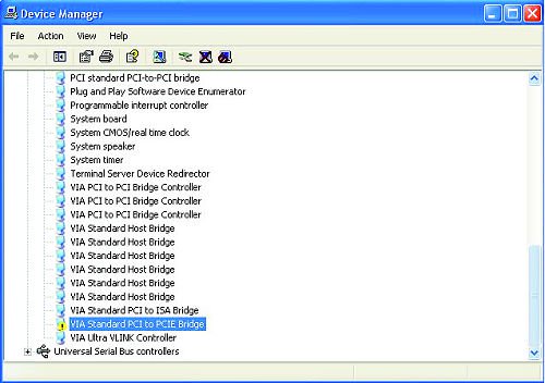
2:The yellow exclamation mark in Device Manager is unnecessary. It will not affect the system at all. Please follow below steps to remove it.
Right-click "My Computer" on your desktop, and click "Properties".
Select "Hardware", and click "Device Manager".
In "Device Manager", double-click the option "System Devices". You will find "VIA® Standard PCI to PCIE Bridge" item with a yellow exclamation mark.
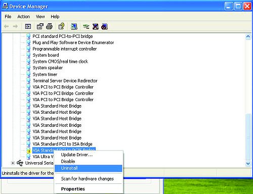
Right-click "VIA® Standard PCI to PCIE Bridge", and select "Uninstall". Confirm your choice by clicking "OK".
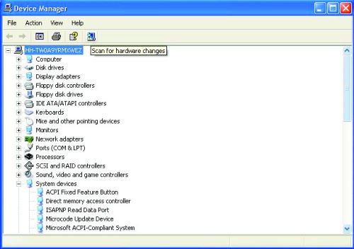
After a few seconds, click "Scan for hardware changes" icon on the top.
Q (Q&A-35|151):
I use an AMD Sempron 2500+ 64bit CPU with K8Upgrade NF3/ K8 Combo-Z/ K8Upgrade-VM800/ K8Upgrade-PCIE/ K8Upgrade-1689/ K8A8X-M motherboard. According to the specification of the boards, it supports CPU Vcore adjustment and CPU multiplier setting functions. However, the "Processor Voltage" and "Processor Multiplier" options are showed as gray in BIOS, I can't change it. Why?(9/20/2005)
A:According to AMD CPU specification, some of AMD 754 pin Sempron 64bit rev. E CPUs (e.g. Sempron 64bit 2500+, 2600+ and 2800+) have only one allowable state on CPU Vcore, so if user plugs in this kind of CPU, the "Processor Voltage" and "Processor Multiplier" options will be shown as gray and cannot be adjusted in BIOS.
Q (Q&A-33|147):
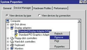
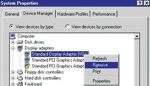
I use PCI Express VGA card on my ASRock motherboard. My operation system is Windows 98SE / ME. In "Device Manager", there are two "Display Adapter Controllers" in "Display Adapters" option. What should I do?(7/15/2005)
A:Please follow the below steps to install PCIE VGA card driver.
a. Please enter "Device Manager" and you will see "Standard Display Adapter (VGA) and "Standard PCI Graphics Adapter (VGA)" in the "Display Adapters" option.
b. Please Choose "Standard Display Adapter (VGA)" and right-click "Remove".
c. After removing the device, please reboot your system. Then, you will only see "Standard Display Adapter (VGA)" in "Display Adapter" option.
d. Please start to install your PCIE VGA card driver.
Q (Q&A-30|137):
I use a PCI VGA card with onboard VGA of K8Upgrad-VM800 for dual monitors under Windows XP. After updating to Service Pack 2, the function of dual monitors does not work. What should I do? (4/8/2005)
A:After updating to Windows XP Service Pack 2, if you want to use the function of dual monitors, please re-install onboard VGA driver. It will solve the problem.
Q (Q&A-28|129):
When I plug a PCI graphics card on P4VM8, it is not able to run dual monitors with onboard VGA under Windows XP. How do I solve it?(2/18/2005)
A:If you want to use dual monitors with both PCI graphic card and onboard VGA on P4VM8 under Windows XP, please update to Windows XP service pack 2.
Q (Q&A-28|127):
My motherboard is P4Dual-915GL. In the manual, it said the AGI Express slot is PCI Express x4. Can I use other PCI Express x1/x2/x4 devices, like PCI Express LAN card or RAID card, on AGI Express slot?(2/18/2005)
A:We have tested x1 PCI Express LAN card on P4Dual-915GL. It is able to work on ASRock AGI Express slot.
Q (Q&A-24|115):
My motherboard is K7S41(GX), what should I set in the BIOS setup to use the on-board VGA with a PCI VGA card for dual monitors function?(10/15/2004)
A:To use on-board VGA with a PCI VGA card for dual monitors function, please enter the "Advanced" -> "Chipset Configuration" -> "Onboard Share memory" and adjust "Auto" to any other values (32MB, 64 MB, or 128 MB) in the BIOS setup.
Q (Q&A-23|112):
My ASRock motherboard supports Hybrid Booster. Is Hybrid Booster a utility to install? Where can I get it?(9/14/2004)
A:The Hybrid Booster features supported on each models are a little different.
Please go to https://www.asrock.com/mb/index.asp and find the specification of your motherboard and check the exact features supported.
Actually, Hybrid Booster is a combination of several features which have already been provided with the motherboards.
1. CPU Multiplier: Adjusted by setting onboard FID jumpers.
2. CPU Vcore adjustment: Adjusted by setting BIOS setup option.
3. CPU Frequency Stepless control: Adjusted by setting BIOS setup option.
4. AGP/PCI Frequency control: Adjusted by setting BIOS setup option.
5. ASRock U-COP: Hardware feature, no need to be adjusted.
6. Boot Failure Guard: BIOS feature, no need to be adjusted.
Please refer to https://www.asrock.com/feature/HybridBooster/HybridBooster.html for detailed explanations.
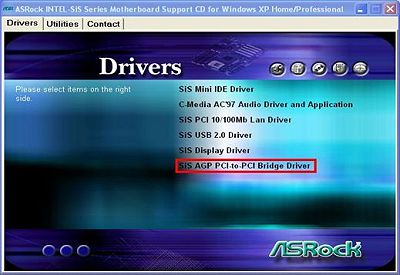
Q (Q&A-22|110):
My motherboard is SiS chipset based motherboard and the driver of AGP PCI to PCI is version 1.16a or 1.13.03 installed. After updating the Windows XP to service pack 2, there is an exclamation mark in AGP driver of device manager. What should I do?(8/16/2004)
A:If you see an exclamation mark in AGP driver of device manager, please simply reinstall the SiS AGP PCI to PCI driver from ASRock support CD or web site again.
Q (Q&A-20|102):
Why is my 4GB of memory reported as about 3.5GB by the system if the chipset of the motherboard support to 4GB Memory size?(6/11/2004)
A:Under the current PC memory addressing, there is a memory area just below 4.0 GB which is reserved permanently. The maximum DDR memory support is actually about 3.5GB rather than 4GB. This limitation is caused by the current PC architecture in which the missing 0.5GB of memory addresses are reserved for PCI I/O space, AGP aperture mapping space, and other onboard device I/O space. Thus although the chipset datasheet may claim memory support for up to 4GB, the system actually only offers about 3.5GB with four 1GB DDR DIMMs installed. 32 bit processors only support 4GB of address space.
Q (Q&A-15|82):
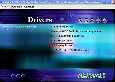
How do I install the display driver for P4S61?(1/14/2004)
A:Please install the display driver by the following steps:
1.Put the P4S61 support CD into the CD-ROM drive.
2.You will see the Main Manu if the "AUTORUN" is enable. Click on the "SiS AGP PCI-to-PCI Bridge Driver"
3.Then install SiS Display Driver.
Q (Q&A-12|65):
I'm using ALi chipset based motherboard, P4AL-8X and P4AL-800. How can I install Linux correctly on them?(10/15/2003)
A:When installing Linux which the Kernel version is order than 2.4.21 on P4AL-8X or P4AL-800, please follow the bellow procedure.
When installing Linux, at the page choosing the installation between "Graphic mode" or "Text mode", please type "boot: linux pci=conf2" to complete the installation.
After the installation, in the GRUB boot up menu, please press "a" to modify the kernel argument. Please type "ro root=LABEL=/ pci=conf2" in order to boot up correctly.
Download the latest Kernel from http://www.kernel.org/pub/linux/kernel/ , for example, linux-2.4.22.tar.gz from another system.
Copy the latest Kernel into this Linux system.
Compile the latest Kernel.
For further Linux information about ALi chipset, please visit
http://www.ali.com.tw/
 Menü
Menü
 (6/26/2008)